РОБОТ НА КОЛЁСАХ MECANUM, УПРАВЛЯЕМЫЙ С ПОМОЩЬЮ ИСКУССТВЕННОГО ИНТЕЛЛЕКТА
РОБОТ НА КОЛЁСАХ MECANUM, УПРАВЛЯЕМЫЙ С ПОМОЩЬЮ ИСКУССТВЕННОГО ИНТЕЛЛЕКТА
Аннотация
В данном исследовании представлена инновационная роботизированная система, объединяющая искусственное зрение, роботизированную руку и колеса Mecanum для решения задач перемещения в динамических средах, требующих точной навигации и манипулирования объектами. Основной целью является разработка единой архитектуры, объединяющей аппаратное и программное обеспечение для обнаружения объектов в реальном времени, отслеживания и синхронизированного управления роботизированной рукой и мобильной платформой.
Система представляет собой изготовленную на заказ мобильную платформу, оснащенную колесами Mecanum с двигателями постоянного тока 12 В, обеспечивающими разнонаправленную мобильность для навигации по сложным участкам местности. Arduino UNO служит центральным процессором и выполняет алгоритмы управления. Производительность системы была оценена в контролируемой среде 5 м × 5 м, продемонстрировав высокую точность калибровки, избегания препятствий и динамического слежения.
Результаты показали, что колеса Mecanum обеспечивают эффективную навигацию в ограниченном пространстве. Данная статья подчеркивает потенциал адаптации робототехники на основе искусственного интеллекта, предлагая ее применение в производстве, здравоохранении, логистике и других областях.
В будущем возможно использование усовершенствованных моделей ИИ для решения более сложных задач распознавания объектов, увеличения грузоподъемности и повышения энергоэффективности, что еще больше расширит возможности применения системы в реальных ситуациях.
1. Introduction
The increasing need for automation in various industries, such as manufacturing, logistics, and healthcare, has accelerated tremendous growth in robotics. Yet, the efficient use of robots in dynamic and uncertain environments is still a major challenge. Such environments tend to require accurate navigation, real-time object perception, and dexterous manipulation capabilities
. This study proposes a novel robotic system that will be used to solve these issues through the incorporation of sophisticated artificial intelligence (AI) vision, a general-purpose robotic system, and a highly agile mobile platform with Mecanum wheels. The main aim of this study is to come up with a cohesive architecture that unifies hardware and software elements to operate robustly and efficiently in dynamic environments . The system employs strong control algorithms for synchronized motion planning and execution of the robotic system and mobile platform driving the Mecanum wheels for effective navigation and obstacle avoidance . Taking advantage of the capability of AI, i.e., deep learning techniques, improves object tracking and recognition capability. This involves training and deploying convolutional neural networks (CNNs) for object detection and tracking, enabling the system to adapt to diverse and challenging visual environments . The proposed robotic system incorporates a custom-built mobile platform equipped with four Mecanum wheels powered by 12V DC motors. Mecanum wheels, with their unique roller arrangement, provide omni-directional mobility, allowing the platform to move in any direction without changing its orientation . Voice-controlled robotic devices usually include an Arduino microcontroller, a Bluetooth module, and an Android device to input commands. The Android device sends voice commands through a Bluetooth connection to the microcontroller, which interprets the commands to drive the movements of the robot. The use of a Bluetooth module enables wireless interaction, allowing the robot to be commanded at a distance . To test the performance of line follower robots, different tests are performed, such as straight line, curve line, and junction tests. The tests determine how well the robot can follow varying path configurations. Successful execution of these tests signifies that the robot can successfully accomplish its intended navigation functions, despite the possibility of technical enhancements at all times . Agricultural robots are applied in various applications, ranging from planting to harvesting, as well as precision spraying. They utilize sophisticated technologies like computer vision, machine learning, and sensor fusion to undertake activities of high accuracy .2. Research methods and principles
Voice-operated robotic systems based on Arduino microcontrollers have attracted considerable interest because of their possible uses in environments that are inaccessible or dangerous to humans. The systems utilize voice commands to operate robotic movements, providing a hands-free and user-friendly interface for users.
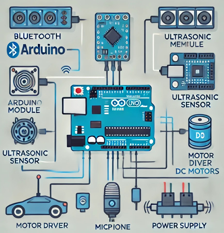
Figure 1 - Block diagram of a Line Follower Robot
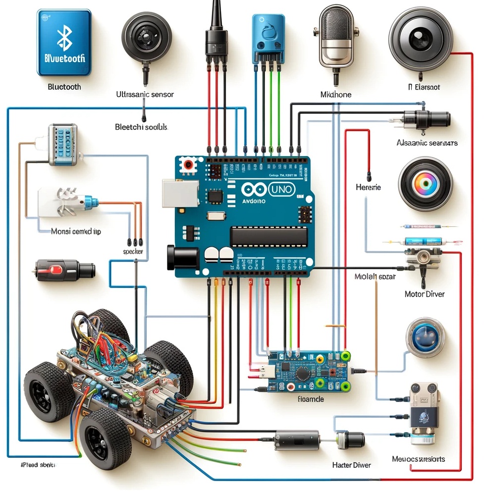
Figure 2 - Line Follower Robot controlled by a smartphone using MIT App Inventor
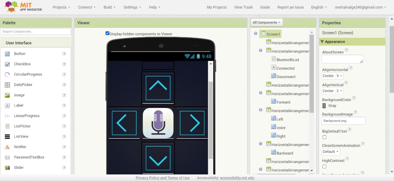
Figure 3 - MIT App Inventor interface
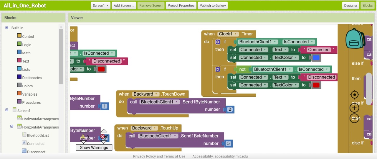
Figure 4 - Development environment of MIT App Inventor
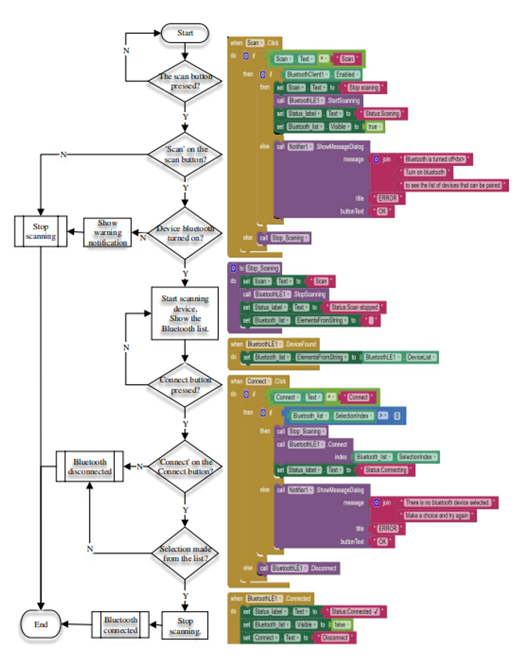
Figure 5 - Bluetooth connection process
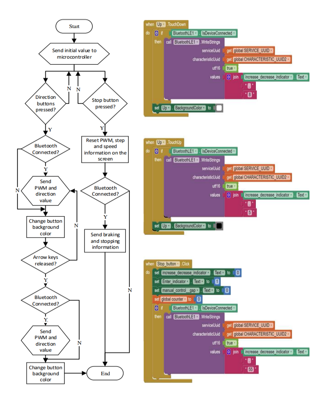
Figure 6 - Control logic for the proposed system
3. Main results
Voice-controlled systems are especially helpful in controlling electronic devices, where users can turn on or off devices with voice commands via a Bluetooth connection on a mobile phone. This method not only makes it easy to control electronic devices but also assists in saving electricity by turning off devices when they are not in use. Further, voice-controlled robots with object identification and picking skills are also in the making to further augment automation in sectors like warehousing and healthcare, illustrating the adaptability and potential of these systems.
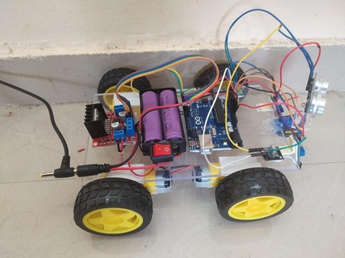
Figure 7 - Line follower robot prototype model
4. Discussion
The system controlled by Bluetooth performed successful operation based on the designed flowchart. Direction button and stop button input from the user was successfully converted into control signals, and a stable Bluetooth connection provided consistent communication with the microcontroller. The system displayed precise motor control, responding well to direction changes and performing the stop command well. Visual feedback through color-changing button colors and on-screen data improved user experience and awareness. Simple error handling mechanisms were implemented to deal with Bluetooth disconnections, providing safe operation by suspending commands until reconnection occurred. In general, the system proved successful, offering an intuitive and robust interface for the control of a microcontroller-based system over Bluetooth.
5. Conclusion
Voice-controlled robots have numerous applications, including military operations, home security, rescue missions, and medical assistance. They are particularly useful in situations where human presence is risky or impractical. They are also useful in helping disabled people, allowing them a method of controlling devices without physical interaction. Although existing systems exhibit good voice control, there are still issues in enhancing voice recognition accuracy, particularly in noisy settings. Future studies may address how to make voice recognition more robust and increase the capability of such robots to accomplish more sophisticated tasks. Moreover, incorporating more advanced technologies like natural language processing could further enhance human-robot interaction.