
Подход, основанный на использовании оболочек, для моделирования проекций трехмерного изображения и его реконструкции
Подход, основанный на использовании оболочек, для моделирования проекций трехмерного изображения и его реконструкции

Аннотация
В описании 3D-объектов для кусочно-однородных структур рассматривается подход, основанный на явном определении границ. Этот способ обеспечивает адекватное описание разделяющих поверхностей между различными компонентами исследуемых объектов. Подход реализован и исследован в общем виде для многоуровневых объектов, имеющих конечное число различных однородных частей и разделяющие границы, определяемые произвольными замкнутыми оболочками, а именно линиями для 2D-задач и поверхностями для 3D-пространства. Результаты тестирования алгоритма представлены с использованием ряда многосвязных 3D-объектов. Применение алгоритма для вычисления нелинейного прямого оператора, связывающего форму исследуемого объекта и его проекции на плоскость детектора, проиллюстрировано на нескольких примерах для многокомпонентных 3D-структур.
1. Introduction
There is a broad class of non-destructive testing problems whose solutions are piecewise constant functions. These objects typically include so-called piecewise homogeneous structures, objects or systems that have various homogeneous parts with constant linear attenuation coefficients, separated from each other by non-intersecting boundaries that represent closed two-dimensional continuous lines or three-dimensional shells. This class includes industrial pipelines, castings, and various mechanical engineering assemblies. For example, one important task is the reconstruction of the internal and external profiles of industrial pipes, which can be defined as continuous shells. From here on, the term "shell" will also be used for the two-dimensional case.
Below, we will examine the key features of the shell reconstruction method and the principles of boundary description, allowing us to take into account important a priori information about the structure of a piecewise homogeneous object. The proposed approach was first described in
, , . This article will describe mathematical algorithms for modeling ray intersections with multiply connected two- and three-dimensional shells and their implementation in the C++ programming language. Specifically, a detailed description of the above algorithm for calculating the direct connection operator between the surface of a three-dimensional object and its projection images will be given.As mentioned previously, X-ray computed tomography has long been widely used to study the internal structure of various objects. Non- destructive fluoroscopic techniques allow for the reconstruction of internal properties of the studied material, such as the linear attenuation coefficient, by solving an inverse problem. The input data are ray integrals measured using linear detector matrices for 2D tomography and flat detector matrices used in 3D tomography. The result of the reconstruction process (inversion of the input data) is a function describing the internal structure of the object.
In computer calculations, discrete models of objects are used to describe the parameters of the medium being studied. Typically, such discrete models are implemented as a system of basic functions defined on a two-dimensional or three-dimensional voxel grid. In general, discretizing the reconstruction space as a finite set of elementary volume elements (voxels) is a natural and proven method for creating discrete models of media. At the same time, there is a wide class of non-destructive testing problems whose solutions have the following characteristic features: the internal structure of objects consists of various homogeneous parts with constant environmental parameters, separated from each other by seamless boundary surfaces.
In this case, using a standard discretization technique based on a voxel-based representation of the object has the following drawbacks: the enormous amount of information required for description in the case of three-dimensional objects, high computational costs, and the blurring of clear boundaries between different materials. This blurring effect can significantly degrade the quality of the reconstructed image of the structure being studied.
It should be noted that a heterogeneous medium can be adequately described by precisely defining the dividing surfaces between homogeneous parts. A surface-oriented description allows for the definition of corresponding structures using closed shells. It should be emphasized that the use of the shell approach for mathematical modeling of the direct problem and for solving the reconstruction problem provides the following advantages:
– this approach allows us to take into account important a priori information about the reconstruction object and more accurately localize the set that contains the exact solution to the reconstruction problem;
– it allows one to describe dividing surfaces in the form of strict and clear boundaries, eliminating the blurring effect and significantly increasing the accuracy of the approximate solution;
– it significantly (by several orders of magnitude) reduces the amount of information required to describe the reconstruction object and the time required to solve the direct and inverse problem (in practice, the reduction in calculation time can reach tens and hundreds of times).
2. Materials and methods
An adequate description of the structures under consideration can be achieved by using the tuple (μ, U). Here μ = {μp} — vector of environmental parameters; in our case μP (p = 1,2, … , P) characterizes the linear absorption coefficients of various parts of the structure being studied. The second element U = {uq} (q = 1,2, … , Q), describing the surface is a set of individual shells uq, which describe the boundaries between homogeneous parts.
Fmsr = {fk}, k = 1, … , K — is the set of measured data on all projections. Then the relationships between the internal structure of the object under study and its projection images for a given configuration of dividing boundaries uq and a set of linear attenuation coefficients {μp} can be determined using the following operator equation:
For X-ray diagnostics, operator A is determined by ray integrals on a family of conical or parallel beams of rays, each of which is projected onto one pixel of the corresponding projection plane. The left-hand side of equation (1) is the calculated data for a given state of the object.
It should be noted that the connection between the object's surface and its projected images is achieved through a nonlinear operator. This property poses a significant challenge when conceptualizing the shell approach. Addressing this challenge requires the development and analysis of specialized adaptive algorithms for solving the reconstruction problem. For example, it is possible to use variational methods for minimizing the residual functional on a given compact set. This entails typical requirements, such as defining the functional class of feasible solutions, selecting the initial approximation, constructing an optimal iterative procedure, and others. As a rule, all these issues are addressed in a specific formulation of the nondestructive testing problem, depending on the nature of the internal structure of the test object. At the same time, it is certainly appropriate and important to fundamentally consider the problems of non-destructive testing for piecewise homogeneous structures in the most general formulation as applied to multi-level objects that have a finite number of different homogeneous parts separated by boundaries defined by closed shells, namely: lines for 2-dimensional problems and surfaces for the 3-dimensional case.
The development of an efficient numerical algorithm for solving the direct problem for this class of test objects simultaneously provides a convenient means for calculating the direct operator A. This calculation is an essential part of the reconstruction algorithm, which is performed at each current step of the iterative process. Furthermore, it is of independent interest for analyzing the relationship between the complex internal structure of various objects and their projection images. Software packages implemented on this principle can be used to solve various non-destructive testing problems.
It is useful to point out two main ways of describing the surfaces of dividing boundaries between different parts of the material being studied:
1) The first approach is a discrete model of the surface as an irregular grid in a Cartesian coordinate system, represented by a set of flat polygons (a 3D CAD representation) or a set of segments for a 2D case. This is a widely known method for describing object boundaries and can be applied for various purposes, such as computer modeling. This approach to surface-based object representation has significant advantages due to the use of complex, non-uniform grids. It can be effectively applied to mathematical modeling of the direct problem and to the analysis of the operator that links the object to its projections.
2) The second approach is a model based on a functional description of the object's boundaries on a regular grid. In this case, discrete surface points are defined using functions that describe the dependence of one spatial coordinate on others on a uniform grid. This model can be implemented in three-dimensional space using functions of two independent variables defined in a Cartesian, spherical, or cylindrical coordinate system. It is advisable, if possible, to use various combinations of coordinate systems to describe various shells defining the boundaries of the reconstructed object or to use vector functions for non-convex parts of the object. Obviously, the use of such a boundary representation depends on the specific test object and the available a priori information. This approach provides a convenient description of surfaces using regular grids of spatial points and can be applied to solving inverse reconstruction problems.
It is possible to propose to use both of the above mentioned types of representation of object boundaries to solve the reconstruction problem, namely: one should use the representation of boundaries on irregular grids for arbitrary complex objects at the stage of calculating the direct operator and apply the functional description at the current step of the iterative procedure for minimizing the residual functional using the available a priori information for the given object.
For the numerical implementation of the shell approach, it is important to develop an efficient algorithm for calculating the direct operator A for a wide class of complex test objects with a piecewise homogeneous structure. For the sake of clarity, we will assume that we are using a conical ray beam in the three-dimensional case and a fan beam in the two-dimensional case. When using a three-dimensional parallel ray beam, the only difference is that the ray hitting the (i, j)-th pixel of the flat projection will be determined by its coordinates (xi, yj), and the direction cosines of the ray, which will have specified values for each projection view. Further consideration will be given to the three-dimensional case, keeping in mind that all definitions and functional dependencies are transferred practically unchanged to the two-dimensional case. Then, for the three-dimensional case, the calculation of the aforementioned operator A requires the determination of ray integrals along the lines connecting the source point with the point of the detector plane:
Let S = (xs, ys, zs) be the coordinates of the source point. The straight line Lij = L (xi, yj) connects the source point S with the pixel (i, j). It should be noted that the integral (2) defines the operator A in equation (1) for a monoenergetic point source S and these integrals are only a component of the operator A for a polychromatic or volumetric radiation source. Thus, equation (2) characterizes the attenuation of an X-ray radiation source for a monoenergetic source and can be used for the same analysis of the attenuation of X-ray radiation from a polychromatic source by additionally considering the energy spectrum of the source and the energy dependence of the linear attenuation coefficient.
We believe (μ, U) is a tuple of two characteristics that describe the internal structure of a piecewise homogeneous medium, where the components of the vector μ = {μp} are constant parameters (linear coefficients weakening) of homogeneous parts of the control object (p =1, … , P) and U = {uq}.
A closed shell is a set of shells between adjacent parts. In the three-dimensional case, we will use a triangulation model on an irregular mesh to describe the surfaces of individual closed shells. In the two-dimensional case, any shell will be a broken line formed by a set of segments of varying lengths.
Equality A (μ, U) = F (x, y) for a multi-level structure that contains P different materials that do not intersect with each other can be represented as follows:
where Vp (x, y) is the optical length of the component material with index p along the line connecting the source S with the point (x, y) on the projection plane. We impose the following restrictions on the class of objects under consideration: any straight line can intersect an arbitrary shell of an object only a finite number of times. For this class of objects, the optical length Vp (x, y) is equal to the finite sum of the lengths of the corresponding segments lying on the line L (x, y), which belong to the material with index p. Therefore, the calculation of the direct operator A in the equation (1) and the radial sum (2) can be reduced to the calculation of the optical length for each individual homogeneous component of the object being studied.
Let a material with a linear attenuation coefficient m be located between the outer and inner shells of a multi-connected object. Then the calculation of the direct operator A can be realized by using the following expression containing the optical length,
F = μV. For multi-level structures that contain different materials, described by the vector {μp} the computational scheme is given by equation (3).
Let us point out that formula (3) was first given by V.P. Zagonov and S.V. Podolyako. They also proposed the initial concept of surface-oriented description of multicomponent objects of complex shape. Later, they used it in other works (see, for example, ), mainly for modeling the process of X-ray radiation passage through complex three-dimensional objects with a piecewise homogeneous structure. During the research, the author of the present work also joined in the development of this approach. Subsequently, the work on further development of this direction was carried out in parallel by two research groups: one from the M.V. Keldysh Institute of Applied Mathematics of the Russian Academy of Sciences, Russia (V.P. Zagonov and S.V. Podolyako) and the second from the Institute of Applied Physics of the National Academy of Sciences of Belarus (V.L. Vengrinovich and the author of this work). It should be said that all research work on the development of this scientific direction was carried out completely independently. The original high-speed mathematical algorithms for calculating the intersection of rays with two-dimensional and three-dimensional shells, as well as the software implementing these algorithms, were created by the author of this work independently and completely independent of similar developments by researchers at the Keldysh Institute of Applied Mathematics. It should be noted that, despite the publications of Zagonov V.P. and Podolyako S.V. known to us, where they outline their concept of this approach, have not published anywhere a detailed step-by-step algorithm for calculating the direct operator for both the two-dimensional and three-dimensional cases, and even more so, nowhere have the source texts of the software procedures implementing these algorithms been provided.
For the first time, detailed mathematical algorithms and software procedures for calculating the operator linking the geometric shape of the shell of the object under study and its projection image on the detector plane are presented in the present paper. We immediately began to develop tomographic methods of shell reconstruction for real objects. The first publication on the three-dimensional reconstruction of the inner surface of a pipe was made in 2001 in issue No. 2 of the journal "Technical Diagnostics and Non-Destructive Testing" (Kiev) . M.E. Zhukovsky, S.V. Podolyako, E.G. Lukyanov, G.-R. Jaenisch and K. Bellon concentrated their efforts on the numerical modeling of X-ray scattering processes in radiographic testing of materials , .
2.1. Modeling projections of three-dimensional objects
Without loss of generality, we can consider the algorithm's features for a single-level (binary) structure. Furthermore, we will even simplify the operator equation somewhat, assuming a single three-dimensional shell. If we have multiple shells, the direct operator calculation can be performed for each one in turn, accumulating the intersection points of rays with shells in a common array, which is then used to obtain ray integrals that take into account the intersections of rays with all three-dimensional boundary surfaces of a piecewise homogeneous object. Thus, the description of the mathematical algorithm for a single three-dimensional shell is sufficient for further consideration.
Let us consider a nonlinear operator equation:
where
where function
Vector
Operator A connects the boundary surface S, defined as the hodograph of the end of the vector
Here
Communication calculation geometric shape of the control and projection shell
To solve the direct problem, we will consider the boundary surface as a set of elementary surface elements:
Each such element is a triangle whose vertices are the nodal points of the discrete lattice. Then
Note that the boundaries of a triangle (i.e., its sides and vertices) do not necessarily belong to this surface element. The projection of a surface element Su onto the n-th detector plane is denoted by
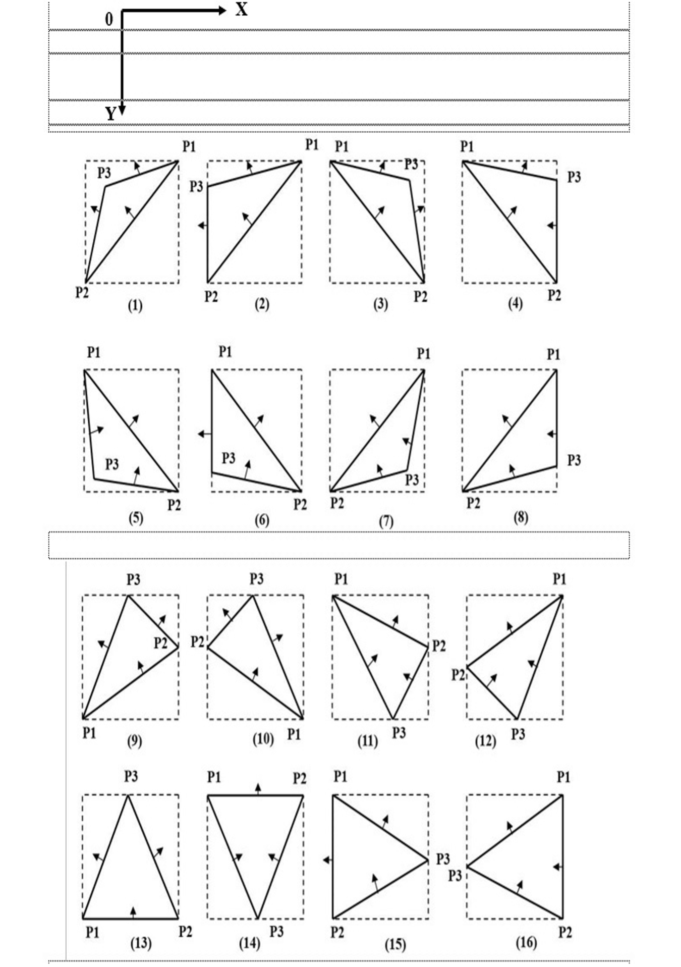
Topological orientation of shadow triangles on the detector plane
a) the projection of the triangle Su onto the current plane of the detectors is found;
b) the boundaries of the triangle are established
c) all pixels
d) the intersection points of the rays passing through the centers of the internal and boundary pixels of the triangle are calculated
Calculating intersection points with a surface is reduced to intersecting the corresponding rays with the plane defined by the element Su. After determining all intersection points lying on a particular ray, they are sorted in ascending or descending order of the parameter of the line on which the ray lies. The number of intersection points for each ray will always be even.
By calculating the distances between corresponding pairs of points and summing them, we determine the ray sum
2.2. The principle of deformation of the surface of a three-dimensional object
A sequential search through all the nodal points of the boundary surface is performed.
where
where
After shifting all the nodal points, Mi we obtain a new discrete lattice
After introducing the next set of corrections,
3. Results and discussion
Below are images of orthogonal sections of a three-dimensional Shepp–Logan phantom and a perspective view of this phantom. The Shepp–Logan phantom projections were calculated using the ray integral algorithm described above in C++. A verification reconstruction of this phantom was also performed, confirming the high efficiency of modeling X-ray projections and, accordingly, reconstructing the phantom image from the model projections.
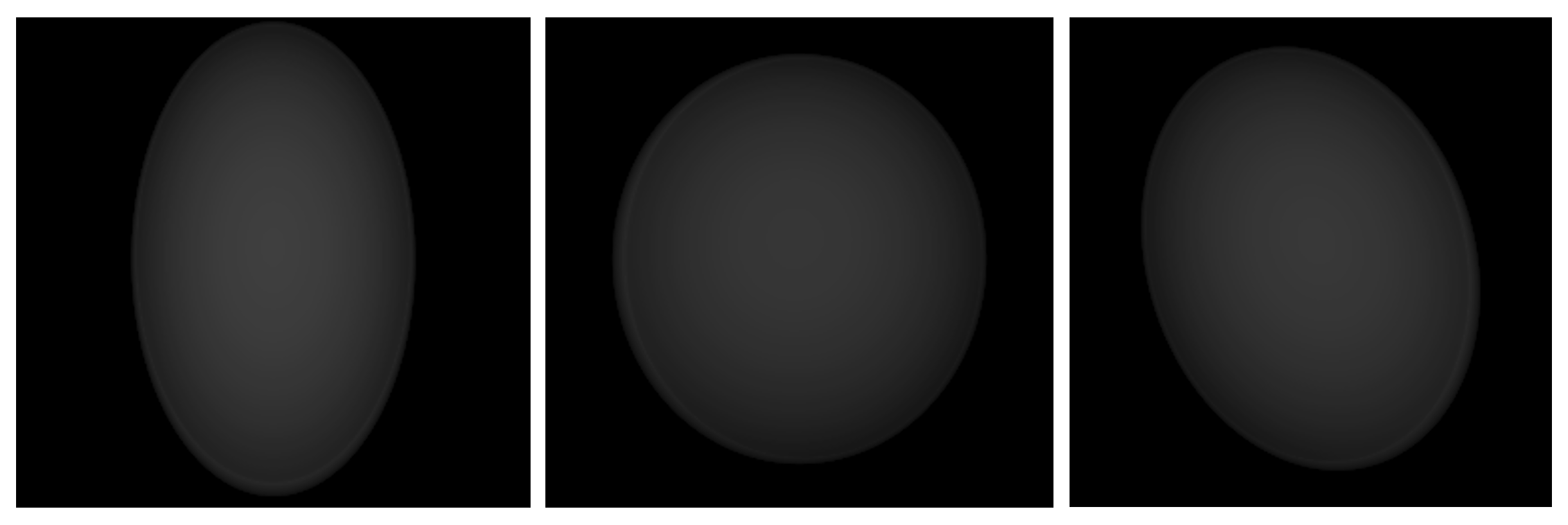
Three model projections of the phantom for planar survey geometry
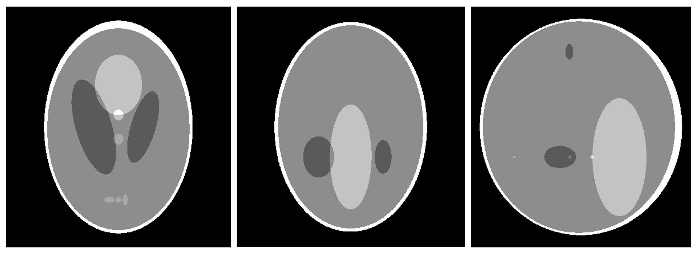
Orthogonal sections of the phantom by planes XOY, XOZ, YOZ
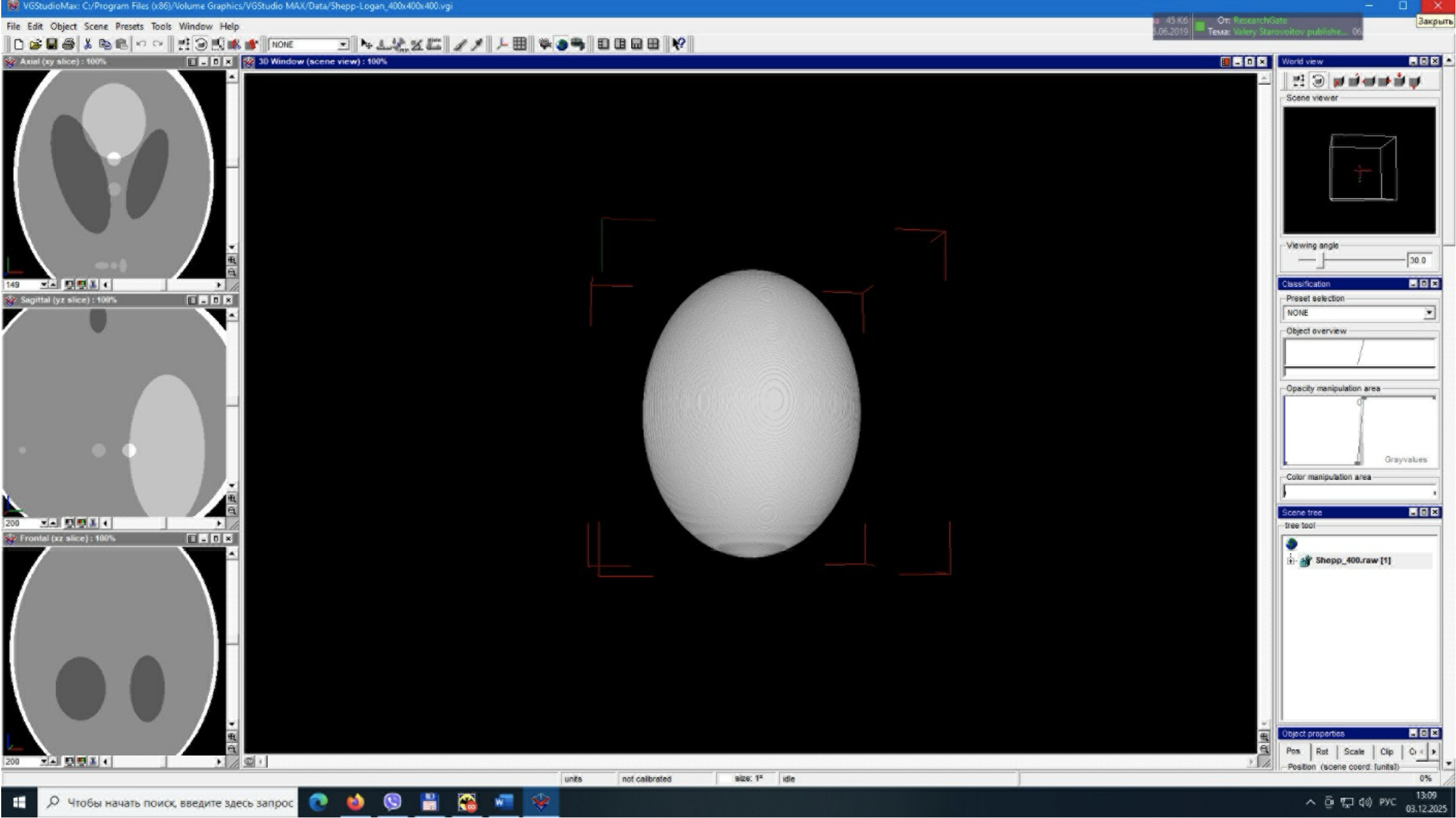
Perspective view of the phantom in VGStudio MAX
As an example, to illustrate how the shell-based tomographic reconstruction method works, we present a image of the central section of a three-dimensional Shepp–Logan phantom. This image demonstrates how, from an initial approximation of the internal homogeneous parts of this object (ellipsoids), which are cylindrical surfaces of arbitrary radius located along the longitudinal axes of symmetry of the ellipsoids, the spatial shape of the reconstructed internal homogeneous parts of this object (ellipsoids) is quickly and accurately reconstructed. Note that each of the reconstructed ellipsoids has a density (linear attenuation coefficient) that may differ from the density of other ellipsoids.
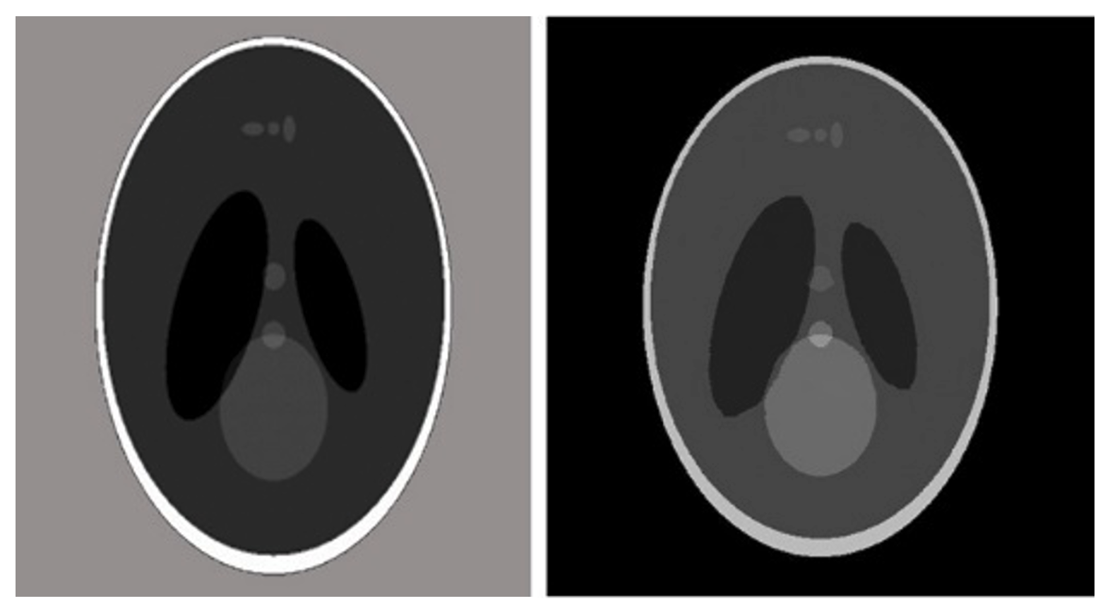
Image Cross-section XOY of the Shepp–Logan phantom illustrating result of the reconstruction process
the original image used to obtain the model projections is shown on the left, and the reconstructed image is shown on the right
Example of reconstruction of the inner surface test tube using X-ray projections contained in a small angular range
The proposed method was tested on a sample from the Institute of Materials Science and Diagnostics in Germany, which consisted of a stainless steel pipe. The outer diameter of the pipe was 112 mm. The wall thickness was 3,6 mm. The inner surface of the pipe had depressions and protrusions of various sizes. To test the resolution of the algorithm, four wires with diameters of 1,8 mm,1,4 mm, 1,25 mm and 0,8 mm were attached to the inner surface of the pipe. The tube was illuminated with an iridium source. The exposure time was 6 minutes. Five images were obtained at tube rotation angles of +45, +25, 0, -25, and -45 degrees. The pixel size of the original images was 50 microns. The source-detector distance was 1604 mm, the distance from the lower edge of the tube to the detector plane was 12 mm, which resulted in relatively strong scattering. For this geometry, the radiation source can be considered a point source, i.e., illumination was performed by a conical beam. The linear attenuation coefficient of the pipe material μ was 74,8 m-1. For reconstruction, the images were converted to a larger grid. The pixel size of the new images was 0,2 mm. The image size was 593x299 pixels. The inner surface discretization was 1200 points along the angle, and 213 points along the ordinate axis (0,3 degrees and 0,3 mm is the size of the intervals by angle and coordinate). The number of inner surface elements was 508800. The number of iterations was typically 10-15. The calculation time on modern computers is approximately 10-15 minutes. This time can be significantly reduced by using additional RAM.
The residual functional was minimized to a value of 0,0785. Direct comparison with the actual object revealed that the reconstruction error was approximately 2%, and the artifact magnitude was 1%. The average deviation of the reconstructed internal radius of the pipe from the true value in areas where there were no protrusions or depressions was 0,1 mm.
Figures 6–8 show the experimental projections with the intensities of unabsorbed radiation. Figure 9 shows the reconstructed inner surface of the pipe, rotated by the polar angle.
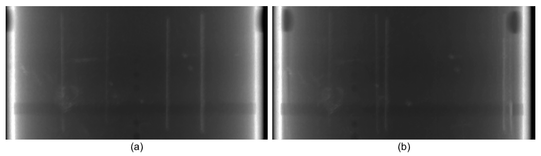
Projections with intensities of unabsorbed radiation for angles of 0 degrees and 25 degrees
a) projection for an angle of 0 degrees; b) projection for an angle of 25 degrees
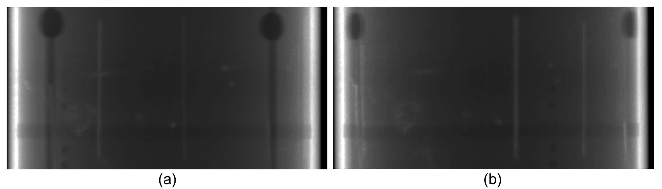
Projections with intensities of unabsorbed radiation for angles of 45 degrees and -25 degrees
a) projection for an angle of 45 degrees; b) projection for an angle of -25 degrees
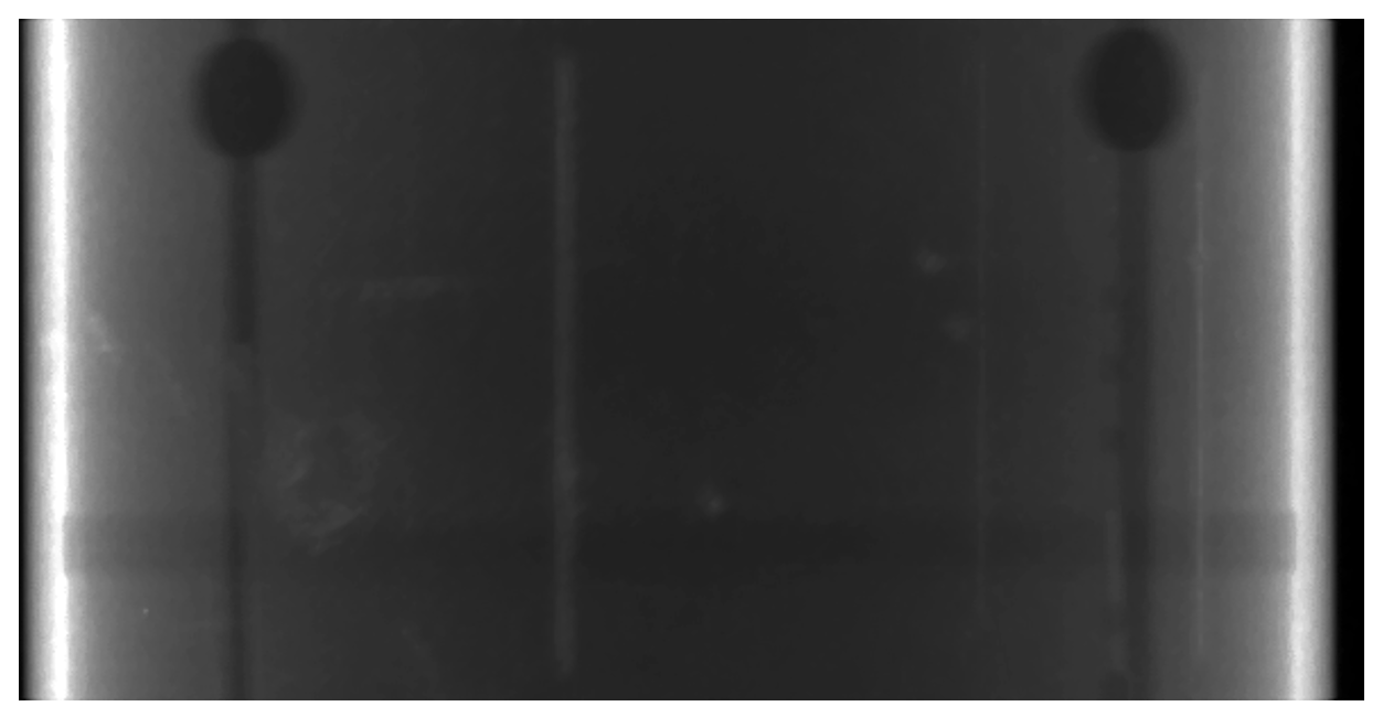
Projection with intensities of unabsorbed radiation for an angle of -45 degrees
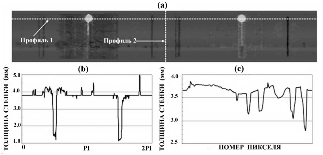
Reconstructed inner surface of the pipe, rotated by the polar angle
a) development of the pipe together with the geometric arrangement of two profiles; b) pipe profile around the circumference – (Profile 1); c) pipe profile along the longitudinal axis – (Profile 2)
4. Conclusion
The boundary description approach based on the explicit definition of boundaries has been proposed and investigated for piecewise homogeneous structures. This way provides the adequate description of the separating surfaces between different components of the studied objects and gives evident computational advantages. The main features of this surface representation approach, difficulties of its realisation and principles for taking into account the essential a priory information have been analysed. The algorithm for solving the 3D direct problem was proposed and realised for widespread model of cone-beam X-ray NDT. It allows considering the multi-component objects, which have a finite number of different homogeneous parts and the separating boundaries defined by arbitrary closed surfaces. The algorithm can be used for analysis of the connection between the internal structure of various objects and its projection images. It was applied to a number of the reconstruction problems of piecewise homogeneous structures with unknown medium parameters and separating boundaries. This article discusses a method for modeling X-ray projections from piecewise homogeneous objects that can be described by closed, non-intersecting three-dimensional shells filled with materials with constant linear attenuation coefficients, which may vary for different shells. The shells are described by spatial meshes of triangular elements. An algorithm for calculating ray intersections with three-dimensional shells is described, enabling the calculation of intersection lengths for modeling ray sums (integrals) on the plane of two-dimensional detectors. A topological diagram of possible locations of triangular element projections on detector planes is presented, enabling the determination of the affiliation of boundaries with a triangular surface element based on its projections onto the detector plane.
The possibility of reconstructing piecewise homogeneous objects by deforming the boundaries of shells containing material with a constant linear attenuation coefficient for each individual shell is demonstrated. Examples of reconstruction for a three-dimensional Shepp–Logan phantom and a test tube from the Institute of Materials Science and Diagnostics in Germany are given.